Looking into the Light!
This month we look into the light to discover how Diamond's new Imaging and Coherence beamline is helping scientists see with greater clarity than ever before! We hear how the beamline works to provide greater resolution imaging, how rocks deep beneath the Earth's surface can be analysed for potential storage of carbon dioxide in the future, and how imaging the internal structure of metal alloys could help recycle them on a greater scale. Plus, the latest news and events from Diamond including new eye-opening research on the cornea and the family history of the virus!
In this episode
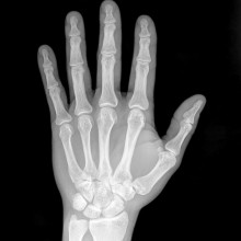
01:35 - Introducing the Imaging and Coherence Beamline
Introducing the Imaging and Coherence Beamline
with Graeme Morrison, Diamond Light Source
Meera - This month we are taking you to the cutting edge of synchrotron science as we explore Diamond’s Imaging and Coherence Beamline where x-rays will soon allow scientists to see, with greater clarity than ever before. The beamline goes into operation in October for use across a wide range of scientific disciplines. Graham Morrison chaired the User Meeting Group for the beamline, and he explained just why the imaging offered is so unique.
Graeme – There are 3 ways in which images can be formed and x-ray imaging has been a long-established technique of ours since Röntgen discovered x-rays at the end of the 19th century. The 3 principle ways are; to form a shadow projection, you know like a hospital radiogram, where you simply have a parallel beam of x-rays going through the sample and you get absorption by certain areas – you get areas of light and dark. A more sophisticated method is to use some form of lens and with x-rays that is already a challenge because x-rays through lenses are quite difficult to fabrigate. With a lens in place in the beam path, effectively you can get magnification. Instead of just getting a life-sized image, a one-to-one image the way you would with projection, you can get a magnified image of the object you are looking at.
And the 3rd way which is newly being developed and explored over the last few years is a process known as coherent diffraction imaging where essentially you don’t try and form an image directly, what you record is the diffraction pattern from the object then use computer algorithms to try a reconstruct the image from the diffraction data that you’ve recorded. Now because that doesn’t involve any form of lens in the beam path, it means you are not limited in the same way that you are if you are using lenses and the technical capabilities of the lens. So in principal, you can get much better resolution from those reconstructions, but it does depend on the reliability of the algorithms that are used for that process.
Meera - And this latter process then, using diffraction patterning, that’s what the new Imaging and Coherence beamline at Diamond will be taking on board?
Graham – Well the Imaging and Coherence branch is intended to do both conventional imaging and to use this new approach of coherent diffraction imaging, as it’s called. So there are 2 branches on the beamline I13, one branch, the imaging branch obviously, will do the shadow projection imaging, which is a very straightforward technique and can yield very useful information. It allows us to look at samples with a big field of view, so that means you can look at perhaps millimetre sized objects.
Meera - But this new beamline, it does have 2 branches, it has the imaging and the coherence, what is different or unique about the coherence side of things.
Graeme – The coherent diffraction imaging branch, which is the, er, if you can record the diffraction pattern successfully and then use these computer algorithms to reconstruct the image, that will take you down to about 5 nanometres which is much higher than you can achieve with any focussing optic. So again, it allows you to address a new range of samples, or get you information about samples that is not currently readily achievable. But traditionally until now, until very recently, that’s been limited, but a new method that’s been developed in the last few years, known as Ptychography, developed principally by John Rodenburg at the University of Sheffield, has allowed the coherent diffraction method to be extended to look at much larger areas of sample and the idea is that you illuminate, produce a spot of x-rays on the sample, you’ve recorded the diffraction pattern from that area and then you step the spot over the sample so that each successive diffraction pattern comes from an overlapping area of the sample. And it turns out that if you do that, then the methods of reconstructing the image data from the diffraction pattern works much better and converges more quickly to a reliable answer. So this allows you to get lens-less imaging of samples at very high special resolution and also to look at extended areas of sample. So I think the application of this sort of an approach on the coherent diffraction imaging beamline will be a very important development.
Meera - How would you then just summarise the main benefits of this new beamline and the fact that it has these 2 branches?
Graeme – In a sense, it’s covering such a huge range of length scales, from the millimetre scale with the projection technique, right down to the nanometre scale with the coherent diffraction, and imaging and ptychography, as a result, it’s also going to cover a huge range of different types of sample from engineering materials down to nano-materials. I think it is actually a beamline that is attractive to the whole range of users.
Meera - Graeme Morrison, Chair of the User Working Group for Diamond’s Imaging and Coherence Beamline.
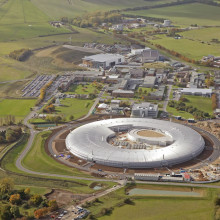
06:08 - On Location at the Imaging and Coherence Beamline
On Location at the Imaging and Coherence Beamline
with Christoph Rau, Diamond Light Source
Christoph – So we are at the Beamline I13 for Imaging and coherence, and the purpose is imaging on the micro and nanometre scale.
Meera - So we’re currently just out on the outdoor grounds of Diamond and the synchrotron is quite a distance away from us. We can see it, so we’re now about 150m or so away. So this beamline is quite unique in itself in that it’s located out of the light source, it’s at this distance, and the hutch over there is about 250m?
Christoph – That’s correct. The reason for doing so is we want to make use of the property of coherence of light and for doing so you have to have a.) a very small light source and b.) to be very far away to have a large, lateral coherent field and that’s exactly why we are so far away.
Meera - So what do you mean by coherence?
Christoph – Coherence is a property of light. Light might have different characters, one is the feature of being a light particle or light might be considered as a light wave and then in this case we talk about coherence light.
Meera - So by coherent light, you mean light in its wave-form, not particle?
Christoph – Correct
Meera - and how is a beam of light maintained at such a large distance? So we’re currently about halfway between the light source and the beamline hutch, so we’re about 150, maybe about 125m away. We are stood on top of concrete and below us, within this concrete, are the tubes in which the beam of light will be travelling. What happens at either end of this tube to keep this light travelling straight through?
Christoph – Ok, so at the beginning we have the light sources which are undulators and each undulator generates the x-rays and they are canted to each other in a slight angle and further they propagate on the beamline, the more they get separated and to increase further the separation we put some mirrors at the beginning of the beamline so that at the end, where we are standing here now, we have roughly a separation of 4 metres between the two different branches.
Meera - So you have 2 beams of light coming over the hutch here from the source?
Christoph – That’s correct, yes
Meera - So if we just move into the actual hutch now to see the type of research that can take place at this beamline. There are 2 hutches at this beamline; and imaging and a coherence one. We’ve come through to the imaging one, but what kind of imaging will take place here?
Christophe - So on this branch, we have the now partially coherent light arriving on the sample and while the light is going through the sample, the light wave is deformed and what happens is that around the edges of the structures, the structures get enhanced, the light wave is deformed and then you can easily detect with a detector these enhance structures.
Meera - Therefore quite clearly seeing the edges and therefore the shape and structure of your sample?
Christoph - That’s correct, and that’s what is called the ‘edge enhancement’
Meera - What kind of samples will be looked at in this way?
Christoph - Basically any kind of sample which is opaque for the eye and which has interesting features on the micro-length scale. Applications are in the field of Biology, for example, Material Science, Geology, there’s a very large range of applications
Meera - And how does this compare to other imaging techniques, even those used in hospitals, so just a simple x-ray?
Christoph - The big difference is the resolution you can achieve. At the hospital, for example, the doctors are interested to learn about whether the bone is broken or not, here we are interested in questions like ‘Why does the bone break?’, ‘What is the mechanism behind this?’, ‘How can you improve any kind of mechanical behaviour?’ and so on.
Meera - Now this is the imaging hutch, but you mentioned there are 2 branches for this particular beamline, also a coherence one, which is about 4-5metres away from her, but in another hutch. What kind of work will be taking place, what will be looked at there?
Christoph - So here, for example, on the imaging branch we will do biomedical applications and Material Science, so we are interested to learn about, for example, cracks in material – that’s very important for Industrial applications, or for biomedical applications what I’m personally interested to learn about is hearing. We will study the mechanisms which are happening inside the cochlea.
Meera - Christoph Rau, Principal Beamline Scientist at Diamond’s Imaging and Coherence Beamline.

Diamond News Update
with Sarah Boundy, Diamond Lightsource
Meera - Let's join Sarah Boundy from Diamond’s Communications Team for the latest news from the Light Source, starting with some eye-opening research...
Sarah – Yes, a group has been studying the microstructure of the peripheral cornea. The cornea is the external lens of the eye, it is responsible for refracting incoming light onto the crystalline lens behind it, which in turn focuses it on to the retina. To function, the cornea needs to be transparent to visible light, it also has to possess high mechanical strength and have precisely defined curvature to focus. The research was carried out by a team from Cardiff University and they were using Diamond’s non-crystalline diffraction beamline I22, and also the ESRF in Grenoble in France. There results were recently published in the Biophysical Journal.
Meera - What were the scientists looking into about it?
Sarah – Well they know that 90% of the thickness of the cornea is made from something called the stroma, which is a thick transparent layer primarily composed of collagen fibrils. So the shape of the cornea is thought to be strongly influenced by the arrangement of collagen fibrils in the stroma and surrounding tissues, and it’s this knowledge that is key to understanding how corneal disease and surgery can affect vision
Meera - So I guess by having a good understanding of the structure, you can see how disease can perhaps damage it and also when reconstructing it with surgery, you can have a better idea of what you’re doing.
Sarah – Well that’s right. The results show the fibril diameter is constant in the centre of the cornea, but increases rapidly when moving out towards the periphery. So this may be an important fact in understanding how the cornea responds to surgery involving peripheral incision, for example cataract surgery. So one of the side effects and complications is astigmatism, and this research will help to explain observations by clinicians that the extent of astigmatic changes depends on the location in which the cut is made.
Meera - So very useful in the post-surgical time as well I guess after corneal surgery. As well as the eye, scientists here have also been looking at viruses.
Sarah – Yes a group has used one of macromolecular crystallography beamlines I03 to look at the ancestry of viruses. So this is research carried out by Oxford University’s Welcome Centre for Human Genetics and it was published recently in Structure. Just as humans have an ancestry, so to do viruses. So the group are currently working at piecing together a complete history of viruses, by solving the 3D structure of the virus proteins.
Meera - So is much not currently known about virus structures?
Sarah – Well viruses are really large, complex structures, so it takes a lot of time and effort to solve the structure of the proteins involved in them.
Meera - Which viruses have they been looking into so far?
Sarah – Well the group have successfully solved the 3D structure of protein D13 from Vaccinia virus which is a member of the poxvirus family. So this protein is a scaffolding protein and its particles, or Virons, take the shape of a sphere as the virus starts to form before D13 is lost and the virus takes on a more brick-like shape. And this is the first time they have been able to determine the structure of the protein D13.
Meera - Why is it useful to know this particular virus structure?
Sarah – Well they found that it has a very distinctive shape, a shape that is also found in large DNA viruses such as human Adenovirus which is a cause of respiratory and eye infections. So by comparing the structural similarities of the different virus’ scaffolding proteins they can determine the lineage of Vaccinia Virus and place it within their virus family tree.
Meera - I guess an application of knowing the structures is to possibly come up with better treatments or antivirals?
Sarah – Exactly. Knowing who or what a particular organism is descended from, can tell us a great deal about how it may function. So in the case of viruses, this kind of knowledge could help us to define new ways to treat them. We could be looking at drugs for patients who are suffering from one of a number of viruses, just in the way we use antibiotic to treat a number of bacterial infections.
Meera - So treating a family of them rather than very specific viruses at a time?
Sarah – That’s right.
Meera - And what about more in-house news for Diamond?
Sarah – Well we now have our summer 2011 Issue of Diamond News, that’s our bi-annual newsletter. This one looks at research using altruistic bacteria, metal-organic frameworks for sustainable storage solutions, and tuneable polymers which are enabling scientists to produce colours without using pigments. There’s also a round-up of some of our PhD students’ in there and some updates on the facility as well, so there’s lots going on. Copies are available from the Diamond website.
Meera - And as well as news updates, you’ve got more multi-media content online as well?
Sarah – Yes, we’ve been working on some new video content. You can see the first instalment which we’ve call ‘We are all scientists’ and that’s on our website education pages. It features clips of scientists and engineers talking about what fascinates them about science and what they think about the Diamond synchrotron and why it’s important to them.
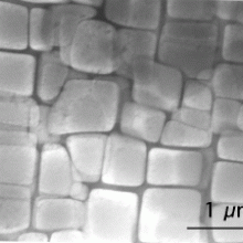
16:34 - The Structure of Alloys
The Structure of Alloys
with Peter Lee, University of Manchester
Meera -Now we meet Professor Peter Lee from the University of Manchester who’s hoping to use Diamond for some clarity about the structure of metal alloys.
Peter – I study the solidification of metals, the processing of metals as well as other materials. In doing that, there is all sorts of kinetic reactions happening and microstructures forming. So the strength of any alloy is not just in its composition, but that composition causes it to form small crystals, different phases, and those phases, very often, are nanostructures. So the strengthening goes from a scale of 10 nanometres where you have small precipitants which are pinned and in fact in alloys, nano-reinforcements has been used for over 103 years now and that then evolves and goes up to a scale of microns and then up to a structure and scale of millimetres. I use Diamond in order to investigate the composition, morphology and interaction of these different phases of these structures.
Meera - And what particular alloys do you look into, focus on?
Peter – One of the main ones I look at is aluminium alloys. These alloys are used in everything from automotives through to air space components. The bulk of these alloys in high-performance applications has been using primary aluminium. The reason they use primary aluminium instead of secondary or recycled aluminium is that when we recycle aluminium we almost as people are slipping in various different stale components. It also just comes through when you break up and recycle an automobile you end up with, very simply, nuts and bolts which are almost always steel. We then re-melt it, the iron concentration in the alloy goes up. Adding that iron concentration, as soon as it goes over 0.5 weight percent, starts causing another phase that when it’s very fine can be reinforcing, but when it’s large can actually be detrimental to the properties. It forms a phase which is highly facetted, it has flat planar edges, so it’s like a diamond, but the phase it forms, instead of being like a diamond and being nice a chunky, is elongated, or needle like. Now imagine structures which are very pointy inside of a material, they act like stress concentrators so they can actually mis-shape, create damage and cause early failure.
Meera - And now knowing this information are you trying to see what’s possible to make recycled aluminium more desirable?
Peter – Exactly. These structures go from nano and when they’re nano they’re beneficial. When you start getting the iron level up, they can actually become as long as 200 microns, almost a millimetre, long and it’s when there are these long sharp shards that they can be detrimental. What we are using Diamond for is in order to determine how we can alter the composition, go through and add a very small percentage of the different alloy compositions or add heterogeneous nuclei that will convert these from a few large structures to many very fine structures and convert something that’s detrimental to something that’s’ actually beneficial within the alloy. If we can do that, we can make the recycled alloys as useful as the primary aluminium alloys.
Meera - And how much of a challenge is that? What do you need to do to go in there and break those long shards and increase the strength around there as well?
Peter – It’s a tremendous challenge. These alloys have 6 to 8 different components. Each of these components are varied in a weight percent from a few parts per million, up to, going to, 1000 parts per million. If you now think of a sort of combinatorial experiment where you are varying from parts per million through to thousands of parts per million with 8 different components, very quickly you can work out that it is actually billions of experiments you can perform in different compositions. What we’re using Diamond for, is to directly observe the kinetics to determine what are the critical phenomena. It’s a real challenge because the few things that we predicted do seem to be probable, aren’t stable in molten aluminium. Molten aluminium has a great ability to dissolve many, many things within it. You also have to be able to make these particles at a very tiny size and get them into this molten melt which means that you need to be able to have them fully leaded by the aluminium. So, there’s lots of challenges we’ve got, lots of great science to carry on doing.
Meera - But what are the benefits of using increasing amounts of recycled aluminium alloys rather than primary sources?
Peter – The huge benefit of using recycled aluminium is that when you make the first original primary aluminium, it comes from digging up bauxite, reducing the bauxite to alumina. Then taking the alumina, which is basically one aluminium atom to 2 oxygen atoms, and reducing that. When you do that, each of those oxygen atoms is converted into a CO2 atom. You are also consuming huge amounts of energy. All that means is that you’re producing somewhere between 7 and 10Kg of CO2 per kilogram of primary aluminium. When you recycle it, you’re really just re-melting and purifying it. That in general, uses less than 0.5 of a kilogram, or 1/20th of the CO2 that’s released. That, if we can go through and convert just 5% of the World’s primary aluminium production to secondary, in new applications which are high-value-added, mean that we can save 15 million metric tonnes of CO2 per year.
Meera - That’s quite a saving, simply by understanding the internal structure and chemistry of metal alloys. That was Professor Peter Lee from the University of Manchester.

23:25 - The Challenges of Carbon Sequestration
The Challenges of Carbon Sequestration
with Martin Blunt, Imperial College London
Meera - Lets now explore an area of research that could prove essential in our fight against climate change and that’s carbon sequestration. The technique hopes to capture carbon dioxide from Power Stations, compress it into a liquid and store it deep below the Earth’s surface. If proven to be viable, it’s estimated the technique could be used to store 1/5th of our total carbon dioxide emissions. Professor Martin Blunt from Imperial College London has been looking into the challenges of injecting these emissions into the ground...
Martin - Most of our research is concerned with carbon capture and storage as CO2 is separated from fossil fuel-burning power stations, compressed, transported, normally by a pipeline, and then injected deep underground and it is the injection and what happens to the CO2 deep underground that’s the focus of our research.
Meera - What are the challenges associated with injecting liquid carbon dioxide deep into the ground?
Martin - It is very high pressures, so it’s liquid-like, and what we’re injecting it into is porous rock. So I’ve go there a sample of a carbonate rock. The CO2 is injected into the tiny, micron scale, pore spaces of this rock that initially contain brine. So the rock is full of salty water, we inject CO2. It’s the same types of rock that we find oil and gas, indeed we could store the CO2in depleted oil and gas fields as well. The main concern that we have is when we inject the CO2, how can we ensure that it stays underground, that it doesn’t escape to the surface? So what we’re looking at is what happens to the CO2 when we inject it, will it stay underground?
Meera - This model of rock that you’ve got here, this is calcium carbonate? It’s a reasonably small cylinder or I guess, 10cm or so long, but why this particular rock?
Martin - The 2 major rocks in which we find both oil and gas and indeed the major storage of CO2 in aquifers, essentially carbonates, so calcium carbonate, the remains of seashells crushed and chemically altered over millions of years, and sandstones which are mainly silica.
Meera - You’ve mentioned that one of the key challenges or issues on people’s minds is whether this CO2 will stay down in the ground once it’s there, so how have you set about investigating how long it will stay there or whether it will be stable?
Martin - We’ve looked at the CO2 in the pore space of the rock at the micron scale. That’s why we’re using Diamond. So what I have here is the special flow cell we’ve used to study. So what we do is we take a very small sample of rock, I’m looking here now at a piece of rock that’s about 5mm across, about a 1cm/1.5cm long.
Meera - So a miniaturised version of your cylinder from earlier?
Martin - Yes, we’re not just imaging the rock, we want to image the fluids and what’s new about this setup is that we’re imaging the fluids at reservoir temperatures and pressures. So the temperatures are about 50°C, the pressures are about 100x more than atmospheric.
Meera - This must be quite hard then to simulate?
Martin - Yes, so what we do is we take the little bit of rock, we wrap it in a sleeve very tightly and we inject fluids at very high pressure. How do we contain all of this? What we do is have another jacket of water that’s at high temperature and pressure and we surround all of that with carbon fibres. Carbon fibre is extremely strong, thin and it’s x-ray transparent.
Meera - So just looking at the model here, you’ve got this long carbon fibre tube inside of which you will put your sample and on either end you’ve got steel, larger cylinders, what role are they playing? Are they providing, ‘cause they look like they’ve got connections coming out of them
Martin - Oh yes, that’s exactly what it is. So the bit in the middle, the carbon fibre, is where the x-rays go, the steel at the end is basically to have ports through which we inject the fluids.
Meera - And this is essentially what you take along to Diamond to image directly?
Martin - Indeed.
Meera - So what have you been able to see? So you’ve got these small samples of rock and you’ve injected various amounts of carbon dioxide into them, what have you been able to image?
Martin - Right, so we can see on the computer screen here – this is an example of a sandstone where we’ve had brine and we’ve injected the CO2, so we just look at the CO2 in the pore space and we can distinguish between grain, the brine and the CO2. And what we find is that the CO22 tends to move into the centres of the pore space and the brine clings int he narrow corners of the nooks and crannies and the small pores and the reason is that the water loves the rock. Rock, actually, will soak up water like a sponge, the CO2 doesn’t have such an affinity for the rock and tends to be in the wide pore spaces.
Meera - But then through your imaging, what you’ve seen is that you’re pushing this brine, this water, out and the CO2 is getting stored in, but then the water is coming back in.
Martin - That’s right. So we inject the CO2, CO2 goes in, can it escape? Well, the CO2 isn’t quite as dense as water, so what it’s going to do is move up. When it moves up, it moves out of a pore, what moves in? - brine. The brine, as I’ve said, like the narrow bits of the pore space, it fills the small pores and the nooks and crannies, it leaves the CO2 behind in the big pores and it surrounds the CO2 so you have bubbles, pore space 10 microns to a millimetre sized clusters of CO2 surrounded by brine and then you can push as much brine as you like, that CO2 is not moving. It’s not going anywhere. And that is what we can see directly on these images, you can see these trapped clusters of CO2. And the beauty about Diamond is that we don’t just have 2-Dimensional images, we can do this in 3-Dimensions and we can see the 3-D clusters but they fill about a quarter if the pore space. So what happens is, when the CO2 moves, it leaves behind a trail of trapped CO2 in about a quarter of the pore space. That CO2 can’t really escape because it leaves so much behind
Meera - I guess another challenge is that you aren’t able to see this over a period of another 1000 years, so although you know that the carbon dioxide becomes trapped in this way, how can you be assured that is stays in this way?
Martin - What we can do is we can inject a lot of brine. We can’t wait thousands of years, but we can inject so much brine that it’s equivalent to waiting that long. That is the amount of brine moving through is similar to waiting hundreds to thousands of years. And indeed we’ve done that in this experiment and nothing seems to happen.
Meera - What are some of the timescales of this? The rates in which carbon dioxide will be injected, the rates in which brine will naturally move in?
Martin - Typical power station burning coal at 2-3 gig watts is going to produce something around 9 million tonnes of CO2 a year. Chuck that underground for a period of say 30 years, that’s likely to create a plume of CO2 extending to over tens of kilometres. What we could do is extract brine from the aquifer and then re-inject it to enhance the movement to trap the CO2 and the design would be that within 4-5 years you’ve trapped virtually all the CO2. And you can walk away from that site assured that the CO2 is safely stored. Over hundreds to thousands of years, the CO2 will slowly dissolve, but when it dissolves in the brine, that CO2-laden brine is denser and it will sink in the aquifer. So it’s a kilometre underground to begin with, it’s just going to get deeper and deeper. And maybe over thousands to millions of years, the CO2 might react with the rock and form solid carbonate. What we’re showing is that is gets trapped, it will then dissolve, it will react. So it gets safer and safer, it gets less and less likely to escape over time.





Comments
Add a comment